1Proposal of the problem A good safety valve should be used in general medium with four conditions: 1.1 When the rated discharge pressure is reached, it should be able to quickly and reliably open to the rated opening height and discharge the rated amount of excess working medium. .
1.2 In the open state, the safety valve should be able to work stably.
The safety valve of 1. 3 shall be closed when the pressure is slightly lower than the working pressure, and when the pressure is subsequently raised to the working pressure, the sealing requirements of the protected system can still be met.
When the 1. 4 is closed, the safety valve should be under working pressure to ensure the necessary sealing. Then, when there are suspended liquids, muds, abrasives, etc. with granular liquids and used in high temperature media, the above four conditions should also be met. However, in a flat or tapered seal, it is not easy to guarantee.
With the ball valve, the spherical seal can be well guaranteed. This is because: 1.4.1 The ball valve rotates continuously during the movement. There is no suitable sealing surface for the ball valve on the spherical surface. The sealing surface of the ball valve is only one circumferential line. This allows the ball valve to still provide good sealing for media that accidentally mix into solid particles. In addition, the ball valve has no guiding means, thus avoiding the unstable frictional force that hinders the movement, that is, reducing the hysteresis factor of the valve. At the same time, deformation and sealing failure due to the difference in thermal expansion coefficient between the valve and the valve seat material used in the high temperature medium are also avoided. At the same time, it also reduces the unstable working factors of the valve.
1.4.2 Ball valves have greater advantages when the medium is a suspended liquid, mud, abrasive or the like with a particulate liquid.
1.4.3 Since the ball valve keeps rotating during the movement, the wear is not concentrated in a certain place, so the service life is long. Therefore, the use of the ball valve safety valve in the above medium has special advantages.
The main performance indicators of the safety valve are sealing performance, opening pressure, return pressure or opening and closing pressure difference, opening height, displacement or flow coefficient, and mechanical characteristics. Among them, opening height and displacement are two very important and must be evaluated indicators. It is generally believed that the opening height meets the design requirements and the displacement meets the design requirements. So what is the relationship between the opening height of the ball valve and the displacement? Let's discuss this issue.
2 Discussion of the problem 2.1 When the ratio of the length L of the valve seat hole to its aperture d is L/d 0.5, it is called a thin-walled hole, as shown in Figure 1: The flow through the valve seat hole is: Benxi Metallurgy In the journal of the College, the density flow coefficient of the differential pressure medium before and after the valve seat hole is related to the relationship between the flow coefficient C and the height h of the valve core, and the opening height of the safety valve according to JB7 89 "spring type safety valve coefficient" The opening height of the micro-opening safety valve is 1/40 to 1/20 of the throat diameter. The opening height of the full-opening safety valve can be greater than or equal to 1/4 of the throat diameter.
2.1.1 When the opening height h of the ball valve is (1/40 to 1/20) times the throat diameter, the section shrinkage is small when the liquid passes through the valve seat hole, that is, the local resistance coefficient decreases as h increases. ,.
Therefore, the C =1/ 1 ξ speed coefficient will also increase. Therefore, the flow coefficient increases as the ball valve increases, and the flow rate through the valve gap is: where, the valve clearance area is generally β=45°, as shown in Fig. 2, the speed coefficient is 2.1.2 when the ball valve opening height h is greater than or When the throat diameter is equal to 1/4 times, that is, the valve clearance area is greater than or approximately equal to the throat diameter of the valve seat, the area of ​​the liquid flowing through the valve gap is greater than the area of ​​the liquid flowing through the throat of the valve seat, and the valve clearance at this time The local resistance is much smaller than the local resistance of the throat diameter of the valve seat. At this time, the local resistance of the valve clearance can be regarded as zero, that is, ξ=0. So C =1/ 1 ξ=1, and the liquid section shrinkage coefficient is due to the overcurrent of the ball valve. The section is very rounded so that at the maximum lift, the bottom of the ball still abuts against the top surface of the seat bore. Therefore, the lift of the ball valve is increased, and the change in the section shrinkage of the liquid flow is small. Therefore, it can be considered that for the ball valve, the different section lift coefficient C is approximately constant. So C = constant. This shows that when the opening height h≥d of the ball valve increases, there is no influence on the flow coefficient. Therefore, the flow rate through the valve gap at this time is: where the valve seat hole throat area.
It can be seen from the above formula that when the opening height of the ball valve is h ≥ d, the displacement of the safety valve is independent of the opening height of the ball valve.
2.2 When the length L of the seat hole and its aperture d 4 are called thick-walled holes.
When the flow rate through the valve gap is: where, the differential pressure kinetic energy of the valve gap is corrected by the coefficient of the valve gap resistance coefficient, and the resistance coefficient of the seat hole is recommended to be taken in actual use. As can be seen from Table 1, ξ with h Increase and decrease, and the size of the crucible is determined by the structure of the valve seat. Therefore, when the seat hole is determined, ξ is a constant amount. α will also decrease as h increases. Therefore, C increases as h increases. Therefore, the flow rate Q will also increase.
2.2.2 When the ball valve opening height h≥d /4, because the valve clearance area is greater than or approximately equal to the seat hole throat area, the resistance of the valve clearance can be neglected (because the valve seat hole resistance is much larger than the valve clearance resistance) ), that is, the change in ξ is small and can be regarded as a constant. Therefore, C = constant. At this time, the flow rate is: 3 Test and test method In order to test whether the above theory is correct or not, that is, the opening height h of the ball valve is related to the flow coefficient. We did the following test. The test device is shown in Figure 4. Use clean water as the test medium. The opening height of the ball valve is changed by adjusting the thickness of the limit block in the safety valve. h. The safety valve uses a spring with a small stiffness to ensure that the ball valve can be opened to the maximum height defined by the limit block during discharge. Also, during the test, it can be stabilized at the opening height.
1 water tank 2 filter 3 quantitative pump 4 valve 5 flow meter 6 pressure gauge 7 overflow valve 4 test results and analysis of the actual displacement of the safety valve Q according to the formula or C, the actual displacement theoretical displacement, (test The pump supply amount Q h) test results are shown in Figure 5.
As can be seen from FIG. 5, the flow coefficient C and the opening height h are substantially linear in the relative opening height h/d. This is because when the opening height h/d 1/4, the relief valve clearance area is smaller than the seat hole throat area. Therefore, the displacement of the safety valve is determined by the valve clearance area and is proportional to the valve clearance area, and the valve clearance area is linear with the ball valve opening height h of the safety valve. Therefore, the displacement (flow coefficient) of the safety valve is linear with the opening height h of the ball valve. That is, when the c constant is 0.35, as can be seen from FIG. 5, the flow coefficient c is not linear with the opening height h. This is because when it is 0.35, the valve clearance area of ​​the safety valve and the throat diameter area of ​​the valve seat gradually become approximately equal. Therefore, the displacement of the safety valve is related to the valve clearance area, that is, it is related to the opening height of the ball valve, but the influence is small.
At the relative opening height h/d 0 .35, the flow coefficient does not change as h increases. This is because the safety valve spool area is larger than the seat bore throat area. Therefore, the displacement of the safety valve is determined by the diameter of the throat of the valve seat, regardless of the area of ​​the valve clearance. Therefore, it is also independent of the opening height of the ball valve. Therefore, when h/d 0.35, the displacement of the safety valve is independent of the opening height h of the ball valve.
5 Conclusions According to theoretical analysis and experimental tests, the conclusions of the two are consistent. Therefore, the following conclusions are made: The ball valve opening height h/d opening height h of the 5.1 safety valve has an influence on the flow coefficient c, that is, the displacement of the safety valve is related to the opening design of the ball valve. The displacement is: 5.2 When the ball valve opening height of the safety valve is 0.25 h/d, the opening height h of the ball valve has an influence on the flow coefficient C, but the influence is small. That is: the displacement of the safety valve is approximately independent of the opening height of the ball valve.
The ball valve opening height h/d opening height h of the safety valve has no effect on the flow coefficient, ie the displacement of the safety valve is independent of the opening height of the ball valve. Its displacement is: where C is only related to the structure of the valve seat.
Therefore, when designing the ball valve safety valve, the safety valve structure is carefully designed at h/d to increase the displacement of the safety valve. According to the above theory, the improved safety valve proves to be effective through use.
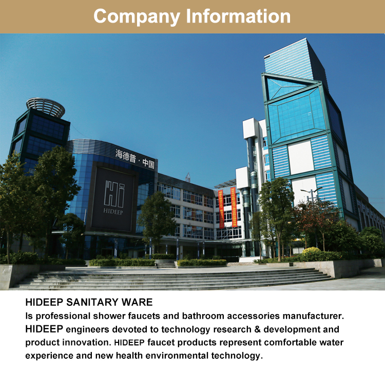
HIDEEP have a wide range of Basin Faucet , including deck mounted basin faucet, wall mounted basin faucet, hot and cold basin mixer, cold water tap and 3 hole basin mixer.
HIDEEP Product line
HIDEEP Product Information
Product description
Basin faucet
Brand name
HIDEEP
Material
Brass main body and zinc alloy handle
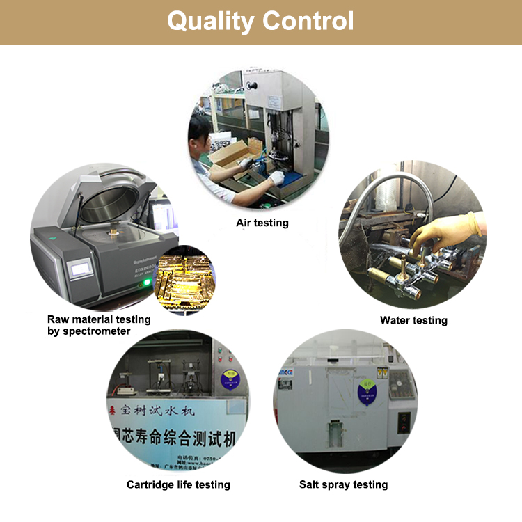
Material analysis
Cu≥59%
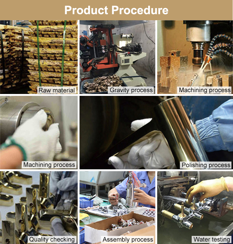
Air pressure testing
0.6 Mpa
The thickness of chrome plating
Nickel>8um Chrome>0.2um
Salt spray test
24 hours
Water flow
Bath/Shower Mixer≥18L/min,
Cartridge life time
300,000 times open and close
Quality guarantee
5 Years quality guarantee
Certification
ISO9001, CE
OEM and ODM
Acceptable
Installation mode
Wall-mounted
Function
Hot/cold water mixer


Basin Faucet
Basin Faucet,Bathroom Basin Faucet,Black Basin Faucet,Wash Basin Black Faucet
Kaiping HIDEEP Sanitary Ware Co., Ltd. , http://www.hideep-faucet.com
