
Roller forgings are one of the most common forging products currently available in forging plants. Today, with the rapid development of the national economy, China's forging technology, especially the design and application of forging molds, has achieved fruitful results. However, compared with foreign advanced technology, there is still a big gap in selecting suitable molds according to product type and production environment. Based on the production experience, the author has made an innovative design for the production of molds for roller forgings.
1. Mold process analysis
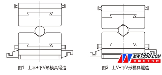
The selection of the roller forging die directly determines the surface quality and internal performance of the forging. In the past, most forging manufacturers forged roller products used for the upper flat plus V-shaped mold (see Figure 1) or the upper V-shaped V-shaped mold (see Figure 2) for forging. The following two types of mold forging often have the following problems: 1 The surface of the forging is not smooth and uneven, which affects the subsequent processing. 2 If the upper and lower molds are not completely aligned, they are misaligned forging, which tends to be shelled on the surface of the forging and affects the internal performance. The surface finish of the 3-roller forgings is slow, and the surface temperature of the forgings is easy to be forged.
In view of the above forging defects, in order to ensure the surface quality, internal performance and production efficiency of the roller forgings, the mold has played a better role, and we have innovated and designed the wrestling to replace the former forging dies.
2. The structure and working process of the mold
(1) The mold structure of the mold structure is shown in Figure 3. The most important part of the structure of the drop mold is the design of the anvil block, the guide post and the spring. These three parts determine the use effect of the drop mold.
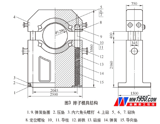
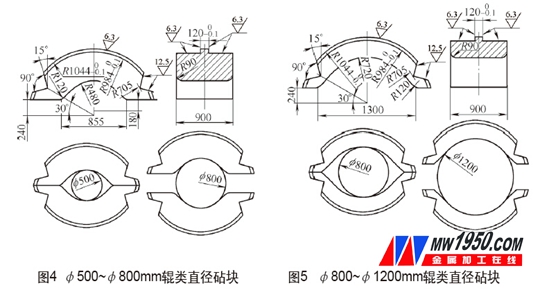
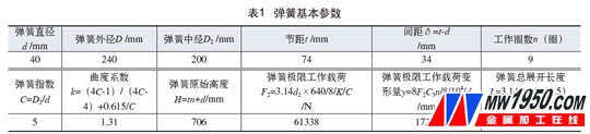
The anvil is designed as a replaceable structure. The anvil is fixed by the oblique iron to connect the upper and lower anvils. When the shafts of different diameters are forged, the anvil can be replaced. The size of the arc of the anvil directly determines the diameter of the forged forgings (see Figures 4 and 5). The minimum diameter of the forged rolls is closed by the upper and lower anvils, and the maximum diameter is tangent to the diameter of the arc.
The guide post mainly serves as a guiding function, and the guide post is coupled with the upper anvil by a positioning bolt, and moves in the direction of the guiding column during the pressing and rebounding process of the upper anvil. The length of the guide post depends mainly on the amount of spring expansion. If the design of the guide post is too long, the upper anvil cannot be compacted until it is closed with the lower anvil, and cannot be forged to the minimum diameter; if the design is too short, under the no-load condition, the upper and lower anvils cannot reach the maximum diameter space, which will affect the use of the drop. effect. Therefore, before designing the length of the guide post, first select the appropriate spring, and when the spring is loaded under no-load condition, select the length of the guide post when the maximum diameter of the forged roller is satisfied.
The spring design is the key point, which directly determines the use effect of the wrestling. It needs to be repeatedly selected and verified. The dimensions of other parts must be designed before designing the spring. The spring design pays attention to two points: 1 When the faller is empty, when the spring is pressed by the weight of the upper anvil and the guide post, the spacing between the upper and lower anvils must be larger than the diameter of the required forging roller. 2 When the hydraulic press is at the maximum pressure of the drop, it must be ensured that the maximum deformation and maximum working load of the spring are less than the ultimate deformation and the ultimate working load.
For example, design 4 guide column 3 spring type drop (suitable for small pressure hydraulic press, large pressure hydraulic press can choose 6 guide column type), hydraulic press maximum pressure + upper anvil + guide column P2 = 85.5kN, upper anvil + guide column P1 = 31kN The height of the guide sleeve is h=40mm. See Table 1 for the basic parameters of the spring.
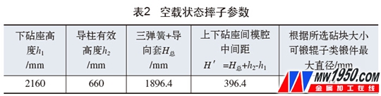
When the wrestler is unloaded, it only receives 31kN of the weight of the P1 upper anvil + guide post itself, and the spring produces a deformation amount y=8×31000×C3×n/8/104/d=87.2(mm). The inner three-section spring structure can obtain three springs + guide sleeve total height H total = 3 × (Hy) + h = 1896.4 (mm). The data of the forging roller forgings at no load is shown in Table 2 and Figure 6.
When the maximum load of the hydraulic press is received, the pressure of the P2 hydraulic press + the weight of the upper anvil and the guide column is 85.5 kN, and the deformation of the spring is y=8×31000×C3×n/8/104/d=240.5 (mm), equally divided into 3 sections. Spring y'=240.5/3=80.1(mm), equally divided to the maximum pressure of 3 springs (4 column bisector pressure, the same force of 3 springs under each guide column) F=85500/4=21375N, not exceeding a single Spring ultimate deformation (172.5mm) and ultimate working load (61338N).
(2) The working process puts the hot roll blank into the cavity between the upper and lower anvils. Under the downward pressure of the movable beam of the hydraulic press, the upper anvil of the falling piece moves downwards according to the direction of the guiding column, and the upper anvil moves to the upper part. At a certain position, when the billet forging diameter is reached, the moving beam of the hydraulic press moves upwards. At this time, the upper anvil is no longer subjected to force, and the spring elastic force causes the upper anvil to rebound to the initial position to complete a forging operation, and the entire roller forging process can be completed by repeated operations.
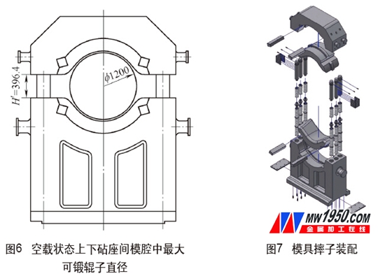
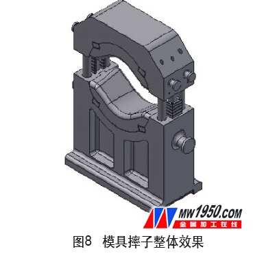
Mold drop assembly and overall effect. The assembly of the wrestling (6-column 4 spring type) (see Figure 7) and the overall effect (see Figure 8).
3. Use effects and advantages
The innovative design of the roller forging die has simple structure, safe and reliable, strong versatility, convenient replacement of the anvil and long service life. It ensures that the surface of the forging after forging is smooth and flat, avoiding the upper and lower molds from being completely aligned, resulting in misalignment. The shell phenomenon, and the forging speed is fast, both in direct forging and finishing, the production efficiency is improved, the production cost is saved, and the first-line workers are favored in production.
4. Conclusion
Starting from the forging process of roller forgings, the problems and causes of the surface quality and internal performance of the forgings produced by the common die forging process are analyzed, and the innovative design of the roll forgings is made. Many problems in production, and the quality of forgings and work efficiency have been greatly improved.
   About the author: Zhou Bin, China's first heavy machinery group company, hydraulic press forging branch.
The advantages of carbide step drills: high hardness, wear resistance, high strength, heat resistance, corrosion resistance, etc.The carbide step drill can quickly complete the drilling and chamfering at one time, which is very suitable for the drilling and chamfering of the threaded bottom hole.
Our company specializes in customizing all kinds of carbide drill bits, carbide twist drills, carbide drill bits, 3 flute carbide drill, metric step drill bit, step drill bit set,stepped drill bit ,etc.

Step Drill Solid Carbide,Carbide Step Drill Bit,Cobalt Step Drill Bit,Solid Carbide Step Drill
ROYI CNC TOOL TAIXING CITY CO.,LTD , https://www.royitools.com