
1 Introduction
The adoption of a unified protocol standard for the CAN bus control network and the Internet is one of the ways in which the CAN bus control network and the Internet are integrated. Currently, it is still an exploratory work. Although the application of embedded control is very extensive, the adoption of a unified protocol standard for the CAN bus control network and the Internet is still a new topic. This approach will be the ultimate solution for the complete integration of control networks and the Internet. Since the distributed control network adopts a protocol standard for different applications, the integration of the two requires a data format conversion mechanism, which complicates the system and does not ensure data integrity. This paper presents the hardware modules of the network measurement and control system based on the CAN bus module, and the software programming ideas of CAN communication.
2 The logical structure module of the hardware system 2.1 The structure of the distributed measurement and control system Figure 1 The structure of the distributed measurement and control system based on the CAN bus The network measurement and control system expands the CAN bus module and has to undertake at least two tasks: First, support on-site operation, including data acquisition , man-machine dialogue, etc.; the second is to interact with the superior node data, as the underlying device of the network measurement and control system. In this paper, a distributed digital measurement and control card based on fieldbus CAN is designed for the process control equipment simulation industrial field of the laboratory. The system structure block diagram is shown in Figure 1.
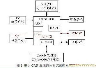
The distributed measurement and control card based on CAN bus is mainly composed of single chip C8051F060, input/output circuit, power supply circuit, man-machine interface and communication interface. The working principle of the measurement and control card is as follows: C8051F060 MCU is a fully integrated mixed-signal system-on-chip MCU, which is an ideal micro-controller for data acquisition and implementation control. It integrates two 16-bit, 1Msps analog/digital converters with a DMA controller; integrates two 12-bit digital/analog converters with programmable data update; integrated controller LAN (CAN2. 0B) Controller with 32 message objects, each with its own identity mask. The state parameters of the industrial field device are converted into voltage signals by I/V. After the C8051F060 MCU collects this signal, it sends it to the upper-level network node through the CAN bus, and the commands and parameters transmitted by the upper-level network node are converted by the DAC and V/I conversion circuit. A 0-20 mA current signal controls the field device. The man-machine interface provides a friendly communication platform between the system state and the operator, and spares an RS-232 asynchronous serial communication bus.
The microprocessor of the measurement and control card is a single-chip microcomputer C8051F060 produced by Xinhualong Company. The series of chips is a mixed-signal system-level single-chip microcomputer integrated on one chip, and its core is a CIP-51 microcontroller fully compatible with the MCS-51 instruction set. The kernel can be developed using the standard 803x/805x assembler and compiler.
In order to increase the flexibility of the system when designing the measurement and control card, the measurement and control card is designed as a way to connect two PCBs together. C8051F060, JTAG interface and its crystal oscillator are independent. The design is called core board on one board. The other application design of the system is called application board on the other board. The core board has formed the simplest single-chip system, which can download and debug the program without the need of peripheral circuits. The application board can flexibly design the peripheral circuits according to the needs of the system, so that the application of different systems needs to be modified only. The application board is fine.
2.2 JTAG debug interface and crystal oscillator circuit There is a JTAG interface and logic in the C8051F series MCU. With the support of the host computer software, the PC directly performs the system simulation debugging on the control system through the JTAG interface. It not only supports FLASH ROM read/write operations and non-intrusive system debugging, but also provides boundary scan function for system testing for JTAG logic. The four pins TDI, TDO, TMS, TCK on the C8051F series MCU are directly connected to the debugging tool serial port adapter (RS232 to JTAG interface module) for program download and debugging. Figure 2 (a) is the JTAG debug interface.
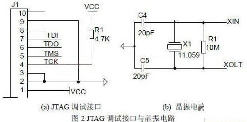
The C8051F060 microcontroller includes a programmable internal oscillator and an external oscillator driver. The system can be divided by an external oscillator circuit or an internal oscillator. After the system reset, the programmable internal oscillator is defaulted to the system clock and corresponds to the fundamental frequency of 24.5MHz. The external oscillator circuit can drive an external crystal, ceramic resonator, capacitor or RC network, or an external CMOS clock can be used to provide the system clock. In order to make the baud rate of the serial communication interface more accurate, the measurement and control card uses an external crystal of 11.0592MHz, and can be connected to the two ends of the crystal with a l0MΩ resistor, making the system easier to start, as shown in Figure 3(b). Show.
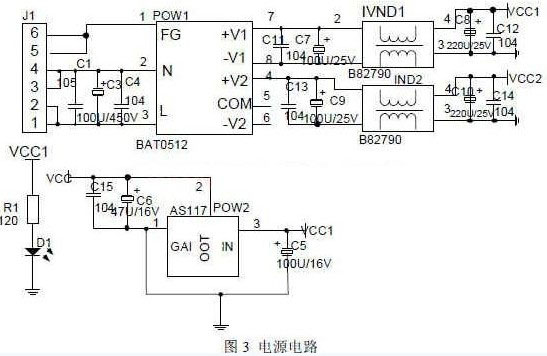
2.4 Power Circuit The operating voltage of the C8051F060 MCU is +3.3V, and the 5V device is also used in the measurement and control system. This paper designs the power circuit shown in Figure 3. First, 220V AC is filtered by the common mode filter and differential mode filter. In order to reduce the electromagnetic radiation during power supply operation, the AC power is rectified into high voltage DC power, and then enter the power module HAT15-05H12-WFCI to get the output +5V and a +12V two. Road DC voltage. +12V is used for ADC circuit and DAC circuit unit, and another 5V power supply is used for 5V devices such as MAX202. The 3.3V power supply part adopts the LDO chip SPX1117M3-3.3, which is characterized by large output current, high output voltage accuracy and high stability.
Metric Nut,Asme metric nut,Metric nuts,Metric nut assortment
Jiangsu Minglu Stainless steel Co.,ltd , https://www.minglubolt.com